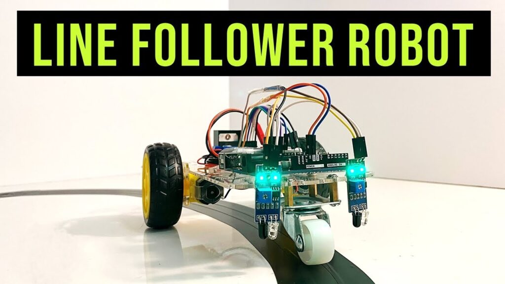
Building a Line Follower Robot Using Arduino : Creating a line follower robot is an exciting and educational experience for anyone interested in robotics and electronics. It’s not just about assembling parts; it’s about understanding how machines can interact with the environment. This article walks you through the process of building your own line follower robot using Arduino, while sharing personal insights and lessons learned along the way.
Building a Line Follower Robot Using Arduino
- Building a Line Follower Robot Using Arduino
- My Journey With Robotics
- What Is a Line Follower Robot?
- Components You’ll Need
- Step-by-Step Assembly
- Coding the Robot
- Testing and Adjustments
- Watching It Come to Life
- Challenges and Key Insights
- Conclusion
My Journey With Robotics
I still remember the first time I tried to build a line follower robot. It wasn’t perfect—far from it. The robot would zigzag uncontrollably, and the IR sensors didn’t seem to cooperate. But through trial, error, and persistence, I finally created something that worked. That journey taught me patience, problem-solving, and the thrill of seeing your creation come to life.
In this guide, I’ll not only explain the technical steps but also share tips and tricks that helped me overcome common challenges. Let’s dive in!
What Is a Line Follower Robot?
A line follower robot is a coding-based robotics project that works according to the program you provide. In this project, the robot is designed to follow a black line on a white surface. The process involves assembling the bot and mounting it on a lightweight chassis (such as acrylic or plastic).
Components You’ll Need
Before we start, gather the following components:
Components Required
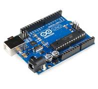
- Arduino Uno:
Arduino Uno is one of the most popular microcontroller boards used in electronics and robotics projects.
Technical Specifications:
- Microcontroller: ATmega328P (8-bit AVR architecture)
- Operating Voltage: 5V
- Input Voltage:
- Recommended: 7-12V
- Limits: 6-20V
- Digital I/O Pins:
- 14 pins (6 of them support PWM output)
- Analog Input Pins:
- 6 pins (10-bit resolution, values range from 0 to 1023)
- Flash Memory:
- 32 KB (0.5 KB used by bootloader)
- SRAM: 2 KB
- EEPROM: 1 KB
- Clock Speed: 16 MHz
- Power Consumption:
- Typical current draw: ~50 mA (depending on peripherals)
- Communication:
- UART (serial), SPI, I2C (TWI)
Physical Specifications:
- Dimensions: 68.6 mm × 53.4 mm
- Weight: ~25 grams
- Connector Type: USB-B (for programming and power)
- Reset Button: Available
Special Features:
- Programming Interface:
- Can be programmed using the Arduino IDE (based on C/C++).
- Power Options:
- USB power or external DC power via a barrel jack or VIN pin.
- Built-in LED: Connected to digital pin 13 (often used for testing).
- ICSP Header: For programming the ATmega328P directly.
- Auto-reset: Resets the microcontroller when a new program is uploaded.
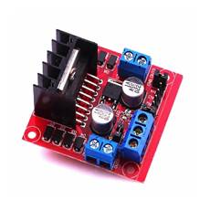
2. Motor Driver L298N:
L298N Motor Driver is a commonly used dual H-bridge motor driver IC/module that allows you to control the speed and direction of two DC motors simultaneously.
Technical Specifications:
- Operating Voltage:
- Logic voltage (Vss): 5V
- Motor supply voltage (Vs): 5V to 35V
- Output Current:
- Max per channel: 2A
- Peak: 3A (short duration)
- Logic Input Current: ~36 mA
- Output Power:
- Up to 25W (depends on motor supply voltage and current)
- Control Inputs:
- 4 input pins for direction control (IN1, IN2, IN3, IN4)
- PWM Frequency: Up to 20 kHz
- Built-in Features:
- Internal protection diodes for inductive load safety
- Thermal shutdown for overheating protection
Pins on the L298N Module:
- Power Pins:
- VCC (Vs): Motor power supply input (5V-35V)
- GND: Ground
- 5V Output Pin: Provides 5V when using Vs > 7V (can power the logic circuit or Arduino in some setups).
- Input Pins:
- IN1 & IN2: Control Motor A (forward/reverse)
- IN3 & IN4: Control Motor B (forward/reverse)
- Enable Pins:
- ENA (Motor A) and ENB (Motor B):
- Enable motor control (connected to HIGH or controlled with PWM for speed control).
- ENA (Motor A) and ENB (Motor B):
- Output Pins:
- OUT1 & OUT2: Motor A terminals
- OUT3 & OUT4: Motor B terminals
Powering the L298N:
- Logic Circuit Power:
- Can draw power from the motor supply when Vs > 7V (via onboard 5V regulator).
- Alternatively, provide 5V directly to the logic circuit (remove the jumper).
- Motor Power:
- Powered via the Vs terminal. Ensure the voltage matches your motor requirements.
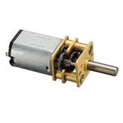
- N20 DC Motors
N20 DC motor is a compact and versatile micro gear motor commonly used in robotics and small automation projects.
General Specifications:
- Size:
- Motor body: 10mm x 12mm x 15mm (approximately)
- Shaft diameter: 3mm
- Shaft length: Varies, typically 8-12mm
- Voltage Range:
- Operating Voltage: 3V – 12V (typically 6V)
- No-Load Speed:
- Depends on gear ratio:
- E.g., 30 RPM to 1000+ RPM at 6V
- Depends on gear ratio:
- No-Load Current:
- 40-150 mA (varies by voltage and gear ratio)
- Stall Current:
- Typically 1-2 A (varies by model)
- Torque:
- Depends on gear ratio:
- E.g., 0.1 kg·cm to 1.5 kg·cm at 6V
- Depends on gear ratio:
Mechanical Details:
- Motor Shaft:
- D-shaped for better coupling with wheels/gears
- Gearbox:
- Built-in metal gearbox with various gear ratios (e.g., 10:1, 50:1, 100:1, etc.)
- Higher gear ratios provide more torque at the cost of speed.
Electrical Characteristics:
- Brushed Motor: Requires simple DC voltage for operation.
- Reversibility:
- Direction of rotation can be changed by reversing the polarity of the input voltage.
- PWM Control:
- Compatible with motor drivers (e.g., L298N, L293D) for speed control using PWM signals.
Applications:
- Line-following robots (like yours)
- Miniature robotic arms
- Small RC vehicles
- Automation projects requiring precise control of small loads
- Jumper Wires:
Jumper wires are essential components for building circuits, especially when prototyping on breadboards or connecting modules in electronics projects.
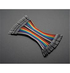
Types of Jumper Wires:
- Male-to-Male (M-M):
- Both ends have male pins.
- Used for connecting components on breadboards or to female headers.
- Female-to-Female (F-F):
- Both ends have female sockets.
- Used to connect two male header pins or modules.
- Male-to-Female (M-F):
- One end has a male pin, and the other has a female socket.
- Commonly used to connect sensors/modules to Arduino or other microcontrollers.
Specifications:
- Wire Material:
- Copper or tinned copper (preferred for better conductivity).
- Insulated with PVC or silicone for durability and flexibility.
- Wire Gauge:
- Typically 22 AWG (American Wire Gauge).
- Suitable for low-current electronics applications.
- Length:
- Varies: Common lengths are 10 cm, 20 cm, 30 cm, etc.
- Connector Type:
- Standard 2.54 mm pitch connectors compatible with breadboards and pin headers.
- Current Rating:
- Typically handles up to 1A of current.
- Voltage Rating:
- Up to 300V for most jumper wires (much higher than typical low-voltage circuit applications).
Applications:
- Prototyping Circuits:
- Connecting components on a breadboard.
- Microcontroller Projects:
- Wiring Arduino, Raspberry Pi, or similar boards to sensors, actuators, or modules.
- Quick Testing:
- Easily swap components without soldering.
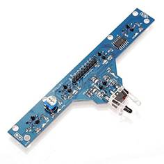
5.IR Sensor Array (5 sensors):
IR Sensor Array (5 sensors) is commonly used in robotics projects, such as line-following or maze-solving robots, to detect lines or track paths on a surface.
General Specifications:
- Number of Sensors:
- 5 IR sensors arranged in a linear fashion.
- Detection Range:
- Typical range: 1 cm to 6 cm (depending on surface reflectivity).
- Best performance on contrasting surfaces (e.g., black and white).
- Output Type:
- Digital output: Each sensor gives a HIGH/LOW signal based on detection.
- Some arrays also support analog output for finer adjustments.
- Operating Voltage:
- 3.3V to 5V (compatible with Arduino, Raspberry Pi, etc.).
- Current Consumption:
- Typically 20-50 mA (entire module).
- Sensor Spacing:
- Fixed spacing between sensors, often around 8-12 mm.
Components:
- IR Transmitter and Receiver Pairs:
- Each sensor consists of an IR LED (transmitter) and a photodiode/phototransistor (receiver).
- Works based on reflected IR light.
- Comparator Circuit:
- Integrated LM393 or similar comparator to provide clean digital signals.
- Thresholds may be adjustable using onboard potentiometers.
- Indicator LEDs:
- Status LEDs for each sensor, indicating detection.
- Output Pins:
- 5 Digital Pins: One for each sensor.
- Some arrays include a combined analog output or serial output.
- Power Pins:
- VCC and GND for power supply.
Features:
- Adjustable Sensitivity:
- Some modules have potentiometers for fine-tuning detection thresholds.
- Onboard LEDs:
- Indicate when IR sensors detect reflective surfaces.
- Compact Design:
- Linear arrangement optimized for tracking lines or edges.
- Versatile Outputs:
- Individual outputs for precise control or combined output for simplicity.
Applications:
- Line Following:
- Detect lines (black/white or contrasting patterns) for robot navigation.
- Edge Detection:
- Prevent robots from falling off edges or surfaces.
- Object Proximity:
- Detect close objects based on reflectivity.
- Maze Solving:
- Use sensor data to make real-time decisions about robot movement.
Step-by-Step Assembly
Chassis Construction Steps
1. Choose Material: Use lightweight materials like acrylic or plastic.
2. Design Layout: Sketch a design that ensures efficiency and smooth turns.
3. Optimize for Performance: Make sure the design supports easy turning.
4. Component Placement: Plan where each part (motors, sensors, etc.) will go.
5. Drill Holes: Drill holes to securely attach components.
6. (Optional): Add carrier boards for a compact and organized assembly.
Tip: Ensure the motors are firmly secured to avoid misalignment during movement.
Steps After Assembly
Step 1: Verify Connections
Check that all connections are correct:
Motor Driver: The red light on the motor driver should turn ON.
Arduino: The Arduino board should light up.
If both components light up, the power supply is correct.
If not, troubleshoot:
Check for loose or incorrect connections.
Test individual hardware components for faults.
Ensure the Arduino code uploads without errors.
Step 2: Test Motors
Before running the full code, test the motors to ensure they work. Use the following sample code to run the motors forward:
#define ENA 5 // Left motor speed control (PWM)
#define IN1 6 // Left motor direction
#define IN2 7
#define IN3 8 // Right motor direction
#define IN4 9
#define ENB 10 // Right motor speed control (PWM)
void setup() {
// Motor setup
pinMode(ENA, OUTPUT);
pinMode(IN1, OUTPUT);
pinMode(IN2, OUTPUT);
pinMode(IN3, OUTPUT);
pinMode(IN4, OUTPUT);
pinMode(ENB, OUTPUT);
// Set motor speed
analogWrite(ENA, 150); // Left motor speed (0-255)
analogWrite(ENB, 150); // Right motor speed (0-255)
// Run motors forward
digitalWrite(IN1, HIGH);
digitalWrite(IN2, LOW);
digitalWrite(IN3, HIGH);
digitalWrite(IN4, LOW);
}
void loop() {
// Motors will keep running forward
}
Troubleshooting if motors don’t run:
Recheck connections to the motor driver and Arduino.
Test each motor individually.
Ensure the correct pins are defined in your code.
Step 3: Move to the Final Code
Once the motors are running, start refining the code:
1. Straight Line Following: Program the robot to move forward when the center sensor detects the black line.
Example code:
if (s3 == 0) {
Forward();
}
2. Test Straight Movement: If the bot successfully follows a straight line, move to the next step.
3. Add Turning Conditions for Right Turns: Use the following logic for turning right:
if (s5 == 0) {
TurnRight();
}
if (s4 == 0 && s5 == 0) {
TurnRight();
}
if (s1 == 1 && s2 == 1 && s3 == 0 && s4 == 0 && s5 == 0) {
TurnRight();
}
if (s1 == 1 || s2 == 1 || s3 == 1 || s4 == 0 || s5 == 1) {
TurnRight();
}
4. Add Stop Logic: If all sensors detect white (off the black line), stop the motors:
if (s1 == 1 && s2 == 1 && s3 == 1 && s4 == 1 && s5 == 1) {
Stop();
}
5. Define the Stop Function:
void Stop() {
digitalWrite(IN1, LOW);
digitalWrite(IN2, LOW);
digitalWrite(IN3, LOW);
digitalWrite(IN4, LOW);
}
6. Add Left Turn Logic (if needed): Create similar conditions for left turns using sensors s1 and s2.
7. Fine-Tune and Test: Be patient! Adjust the conditions and code for smooth line-following.
Testing and Adjustments
1. Create the Line Path
Use black electrical tape on a white surface to create the path. Keep the tape width around 4 cm.
2. Calibrate the IR Sensors
- Place the right IR sensor on the black line and adjust its potentiometer until its LED turns off.
- Repeat for the left sensor.
Pro Tip: Ensure the robot moves forward on a white surface. If it doesn’t, reverse the motor wires connected to the L298N driver.
Common Challenges Faced:
1. Acrylic Chassis Issues: Motors or sensors didn’t function properly due to vibrations or poor surface stability.
2. Faulty Motor Driver: Hardware faults in the motor driver caused problems.
3. Coding Errors: Logical errors in the program needed debugging and corrections.
Challenges and Key Insights
- Battery Selection: A powerful battery ensures consistent motor performance. I recommend a LiPo 2S battery for reliability.
- Line Width: The black line’s width should match the sensors’ detection range.
- Sensor Placement: Keep a consistent distance between the sensors and the surface for accurate detection.
Advancements and Future Improvements
1. Use PID Control: Implement a Proportional-Integral-Derivative (PID) algorithm to stabilize the bot for smoother line following.
2. Enhance the Chassis: Improve material or design for better durability and performance.
Conclusion
Building a line follower robot is more than a project—it’s an adventure. Each step, from soldering wires to adjusting the code, brings you closer to understanding robotics. Along the way, you’ll face challenges, but overcoming them is what makes the experience memorable.
So, gather your components, follow this guide, and start building your own line follower robot today. Share your progress, celebrate your successes, and don’t forget to tweak and improve your design as you go.